
How make smart led bulb|remote control led bulb.

Hello gays welcome to Logic Science, so today we will learn how to make smart led bulb from simple led bulb.To make this project we need a led bulb which we use at home, but here the led bulb we will use is a little different, this led bulb does not have ac to dc power supply circuit board and why is not used is explained below.
 |
Adapter based LED bulb |
We don't used this type of led bulb in this project,Because there is very little space left inside this led bulb, and we cannot install our circuits inside the bulb, so we are not using this kind of led bulb. But you can make this bulb a remote control, in that case you need to insert the remote control circuit into the switch board.
 |
LED bulb without Adapter |
We only used this type of led bulb in this project, Because we get a lot of space inside this led bulb and we can easily install our circuits inside the bulb. This type of led bulb consists of main two electrical components one over voltage protection circuit and other led plate.
 |
Over voltage protection circuit |
 |
LED PLATE |
Over voltage protection circuit is made by two electrical components like MOV or voltage drops resistor,MOV means metal oxide varistor and it's used for over voltage protection.
Let's go we are make a remote control smart led bulb step by step.
Friends we will add three electronic circuits with this bulb in this project,three electronic circuits are
1. 5volt dc transformerless power supply circuit.
2. control circuit.
3. solid state relay like BT136.
 |
Remote control led bulb Block diagram |
Protection circuit:-
The main reason for connecting this circuit is to block over voltage. In case suddenly following high voltage then MOV will be short circuit,and this time current flowing stopped from the output side and current only following through the neutral path.
 |
Over voltage protection circuit diagram |
220v AC to 5v DC:-
This is a transformerless power supply and it is very small and light weight but one disadvantage and that is generate low current so you can't connect a high Power device's in this circuit . You can contact any low power device like- led light, transistors, small size motor etc.Since we need low current we used this circuit.
 |
Transformerless power supply circuit diagram |
Control circuit:-
This is a control circuit diagram it is used for on or off to the led bulb, and this circuit is actually known as a bistable multivibrator .This circuit working principle is very simple, this circuit input pin is connected to tsop pin number one, and the output signal pin is normally high, when tsop receives the signal from the remote then the tsop pin one is sent Tigger pulse to the Q4 transistor, then output signal will be low state and led bulb turn on.
 |
Bulb Control circuit diagram |
Solid state relay BT136:-
BT136 is a product code I'D of triac, triac(AC Switch) is a semiconductor three terminal electronic device.This is a very popular switching device in electrical or electronic industries, otherwise this device has a good feature that current flows in both directions when triggered .triac widely used in switching applications, speed control fan or motor, lamp on/off control, phase control etc.
 |
BT136 solid state relay circuit diagram |
LED Plate:-
 |
LED PLATE |
How do contact these circuits?
 |
Connection circuit diagram |
⚠️Safety Warning
My only request is that you must be protected from electric shock while working, you must use hand gloves, Safety Goggles while working and sit on a plastic or wooden chair while working. Also wrap each circuit with Insulating Tape so that it does not touch any circuit. thank you,Enjoy this project.
CIRCUIT DIAGRAM
 |
remote control home led bulb circuit diagram |
PRATs LIST:-
- BT136 triac 1no
- TSOP 1738 1no
- Q1,Q2,Q3 -bc547
- Q4. -bc557
- C1. - 104j100v
- C2. -100uf25v
- C3. -104pf
- C4. -10uf63v
- R1-1m,R2-150R
- R3-1k,R4-330R
- R5-4.7k,R6-100k
- R7-100k,R8-10k
- R9-10k,R10-100k
- R11-10k,R12-100k
- R13-15k
- D1,2,3,4-1N4007
- D5-5v zener diode
- 5mm LED(for optocoupler)1st you check polarity then install LED .
- 5mm LDR(for optocoupler).
How to make optocoupler 1St step :- follw the image

2nd step:- To make it, take a 15mm long rubber heat sink pipe and place the LED on one side of the pipe and the LDR on the other side.

3rd step:-After this I will heat shrink the rubber heat sink pipe so that the led and ldr are stuck together.

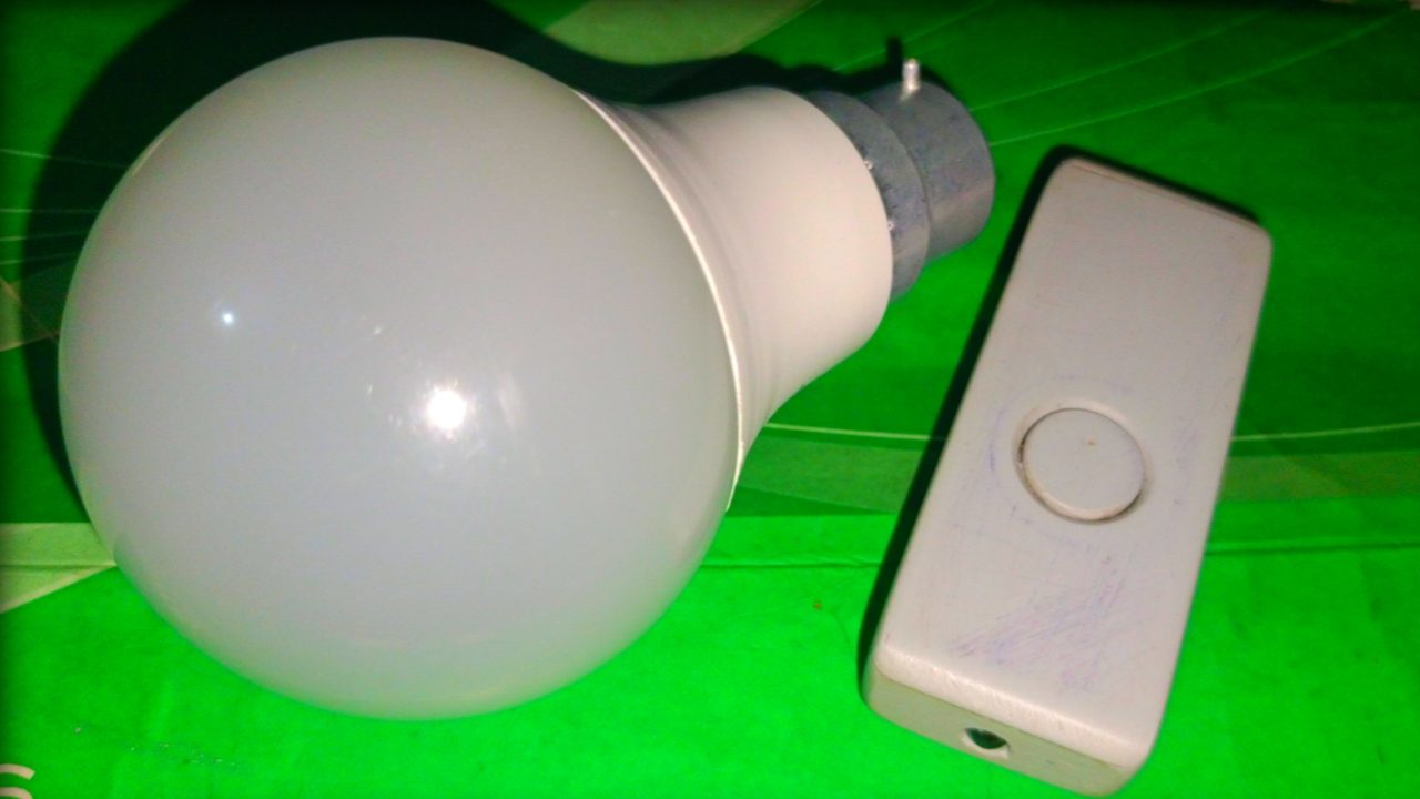
SINGLE BUTTON INFRARED REMOTE
I used 555 timer ic for make single Infrared remote.Do you know why IC is used?
Because the tsop sensor inside the bulb does not work on a fixed infrared signal, if you turn on and off the ir led towards this tsop sensor about 38000 thousand times per second then this sensor works, because the carrier frequency of this 1738 tsop sensor is 38khz/sec. However, the carrier frequency of different TOSP sensors is different. So I used 555 timer ic to generate 38khz frequency which turns ir led off and on about 38000 times per second.
 |
Infrared transmitter project (remote)Single switch remote control circuit using NE555555 timer ic datasheet download |
 |
Infrared transmitter circuit diagram (remote)How to make single button Infrared remote |
Thank you.....


0 Comments